INDUCTION TYPE INSTRUMENTS

The operation of induction type instruments depends on the production of torque due to reaction between two magnetic fluxes having some phase difference OR reaction between flux of an AC magnet and the eddy current induced by this flux. These types of instruments are used only foe AC measurements.
Before getting into the constructional and working details of these instruments; let us first have a general look on the torque produced in these instruments.
The torque produced in induction type instruments depends on the two fluxes; the net torque acting on the disc is
                          \[T=K\omega {{\phi }_{1m}}{{\phi }_{2m}}\sin \alpha \]
Where, ${{\phi }_{1m}},{{\phi }_{2m}}$ = maximum fluxes produced by the currents
               $\alpha $ = phase difference between the two fluxes
And if both the fluxes are produced by the same alternating current, then
                                     \[T={{K}_{1}}\omega I_{m}^{2}\sin \alpha \]
Where, Im= maximum value of current. Therefore, torque is proportional to the square of current for a given value of frequency  and angle . If the disc has spring control, then at some point the controlling torque will be equal to the deflecting torque which will help the disc to attain a steady deflected position. And if the disc is attached to a pointer, then this arrangement can be used for measurement of current.
This was a general discussion about induction type instruments. For the sake of a healthy discussion we will take on these instruments by their types.
Induction type instruments are of two types:
  1. Split-phase type
  2. Shaded pole type


SPLIT-PHASE TYPE –

The diagram for the split phase type induction instrument is shown here.
SPLIT PHASE TYPE INDUCTION INSTRUMENT


CONSTRUCTION –

In this arrangement, there are two AC magnets M1 and M2, which are connected in series. The winding in M2 is shunted by a resistance R.  The current in the M2 winding lags with respect to the total line current. This helps to develop the necessary phase angle $\alpha $ between the two fluxes.


DEFLECTION –

If the hysteresis effects are neglected, then deflecting torque is
                      \[{{T}_{d}}\propto {{\phi }_{1m}}{{\phi }_{2m}}\sin \alpha \]
(Where all the signs have their usual meanings as stated before)
Or, ${{T}_{d}}\propto {{I}^{2}}$ (if fluxes are produced by the same current)
Note that, here I is the r.m.s value of current.
Also, ${{T}_{c}}\propto \theta $ (Because spring control is used)
In the final deflected position, Tc=Td.
 Therefore, deflection ($\theta $)$\propto {{I}^{2}}$


DAMPING –

Eddy current damping is used in this instrument.


SHADED POLE TYPE –

Shaded pole type induction instrument uses a single winding to produce flux. The flux produced by this winding is split up into two fluxes , having phase difference  with respect to each other. The phase difference is usually 40 to 50 degrees and can be varied by varying the size of shading band. This is done by making a narrow slot in the poles of the electromagnet. A copper strip is placed around the smaller of the two areas formed by the slot. This copper shading band acts as a short circuited secondary winding.


CONSTRUCTION –

The constructional features of a shaded pole type induction instrument are shown in the figure below.

The exciting coil is placed on the poles and a current proportional to current or voltage being measured is passed through it. An aluminium disc which is mounted on a spindle is inserted in the air gap of the electromagnet. The spindle carries a pointer and has a control spring attached to it. The controlling torque is provided by this spring only.


DEFLECTION –

As the net driving torque is due to the fluxes and the difference in the phase angle of these fluxes, then deflecting torque can be written as
                         \[{{T}_{d}}\propto {{\phi }_{1}}{{\phi }_{2}}\sin \alpha \]
If are produced by same current I, then ${{T}_{d}}\propto {{I}^{2}}$
As the instrument is spring controlled, ${{T}_{c}}\propto \theta $
For steady deflection, ${{T}_{c}}={{T}_{d}}\Rightarrow \theta \propto {{I}^{2}}$


DAMPING –

Damping is provided by a permanent magnet placed at the opposite side of the electromagnet, so that the disc can be used for production of both deflecting and damping torque.


ADVANTAGES –

  • A full scale deflection of over 300 degrees can be obtained.
  • Good damping.
  • Less effect of stray magnetic fields as the operating fields are large.


DISADVANTAGES –


  • Errors are caused due to changes in frequency and temperature.
  • Non-uniform scale.
  • Large power consumption and high cost.
  • Can be used for AC only.

HOT WIRE TYPE INSTRUMENT

The working of a hot wire type measuring instrument is based on the heating effect of the current. These type of instruments are not much in use nowadays because if their instability in working. Nevertheless, they paved the way for further advancements of their own type.


CONSTRUCTION –

HOT WIRE TYPE INSTRUMENT
The adjacent figure shows the constructional features of a hot wire type instrument. It consists of a platinum-iridium wire AB stretched between a fixed end B and tension adjusting screw at A. The platinum-iridium wire used here can withstand oxidation at high temperatures. Now, a phosphor bronze wire CD is attached or hooked up to the centre of AB. This wire CD is further attached to a silk fiber which after passing round the pulley is attached to a spring S.


HOW DOES IT WORK?

When the current is passed through the fine wire AB, it gets heated up and expands. The sag of the wire is magnified and the expansion is taken up by the spring. This causes the pulley to rotate and the pointer to deflect, indicating the value of the current.
The expansion is proportional to the heating effect of the current and hence to the square of the rms value of the current.


DEFLECTION –

The deflection of the pointer is proportional to the expansion of AB which in turn is proportional to I2.
Hence, $deflection\propto {{I}^{2}}$
As, spring control is used, ${{T}_{c}}\propto \theta $
                                          \[\therefore \theta \propto {{I}^{2}}\]
These instruments read the rms value of current and their readings are independent of its form and frequency.


DAMPING –

Damping is provided by eddy currents produced in the aluminium disc. This thin disc is attached to the pulley such that its edge moves between the poles of the permanent magnet M.


ADVANTAGES –

  • Suited for both AC and DC work.
  • Readings are independent of waveform and frequency.
  • Unaffected by stray fields.


DISADVANTAGES –

  • Sluggish response due to temperature dependent working.
  • High power consumption.
  • Mechanical shocks.
  • They are fragile.
  • Inability to withstand overloads.
These disadvantages have made this instrument commercially unsatisfactory. As such, they are now obsolete and have been replaced by thermo-electric instruments.

KIRCHHOFF'S LAWS


Ohm’s law establishes a relationship between voltage and current. It was one of the simplest equations developed by George Simon ohm. But, ohm’s law alone could not be used to analyze large and complex circuits. Later on, Gustav Robert Kirchhoff (1824-1877) formed the two fundamental laws which are used in writing the circuit equations.
The laws developed by him depend neither on the nature of elements of the circuit nor the topology of the elements (Topology means the way the elements are connected).

WHAT ARE THE TWO LAWS?

They are:
  1. Kirchhoff’s current law (KCL)
  2. Kirchhoff’s voltage law (KVL)

KIRCHHOFF’S CURRENT LAW –

It states that the algebraic sum of the currents flowing across a junction or node is equal to zero. This implies that for the figure given below - ${{I}_{1}}+{{I}_{2}}+{{I}_{3}}+{{I}_{4}}+{{I}_{5}}=0$
CURRENTS COMING TO A JUNCTION

KCL is based on the principle of law of conservation of charge. This is because the amount of charge entering a junction must be equal to the amount of charge leaving a junction; since charges cannot accumulate at a point.
Mathematically, if there are b no. of branches meeting at a node or junction, then
                                          \[\sum\limits_{n=1}^{b}{{{I}_{n}}}=0\]

KIRCHHOFF’S VOLTAGE LAW –

It states that the algebraic sum of the voltages around a closed loop or path or circuit is zero. For a closed loop having n elements,
                                          \[\sum\limits_{i=1}^{n}{{{V}_{n}}=0}\]
KVL is based on the law of conservation of energy. This means that the charges travelling around a closed loop just transfer energy from one element to another, but they do not receive or store any energy themselves. They just transfer the energy.

HOW TO APPLY KCL TO A CIRCUIT?

Consider a node A of the circuit given below:
Then KCL equation for this circuit is written as:
${{I}_{1}}={{I}_{2}}+{{I}_{3}}+{{I}_{4}}+{{I}_{5}}$
The current entering the node is taken to be positive in the equation, while the currents leaving the node are taken to be negative. There is no hard and fast rule so as to determine what sign is to be taken for a current. The point is – if you assume the sign of an entering current to be positive and leaving current to be negative, then follow the same criteria for that particular circuit OR vice-versa.

HOW TO APPLY KVL TO A CIRCUIT?

Consider the circuit given below:

As the circuit is open at terminals a-b; no current will flow in the arms a and b. Otherwise you can also see that no closed loop is formed, so we cannot apply KVL here. But the loop on the left side is a closed loop. Assuming current to be in clockwise direction, the equation is written as –
                                                   \[I{{R}_{1}}+I{{R}_{2}}-V=0\]
Or
                                \[V=I{{R}_{1}}+I{{R}_{2}}=I({{R}_{1}}+{{R}_{2}})\]
BUT HOW DO WE OBTAIN THIS EQUATION?
This equation can be obtained by following these simple steps:

  1. Consider any loop in a circuit and assume the current to be in clockwise or anti-clockwise direction. Generally, the direction of current is inferred by seeing the positive terminal of a higher value of voltage source. Because current is supposed to be coming out of the positive terminal of the source.
  2. Multiply the assumed current variable with the values of the elements which you encounter in your path and write the equation in terms of the sum of these multiplications obtained from each of the element.
  3. For writing the value of voltage source in your path; write positive sign if you encounter positive terminal first and write negative sign if you encounter negative terminal first.

NOTE:

As the equation to be written is a sum of voltages, therefore you need not multiply the current variable with voltage sources.
Only multiply the values of circuit elements namely resistors, inductors and capacitors with current variable.
KCL and KVL form the basic laws for analyzing the circuit. Learning their application to circuits is of immense importance to every electrical engineering student or aspirant. Further, there are more circuit theorems in circuit theory which help to solve circuits. But their application requires the understanding of KCL and KVL. 

SERIES RESISTORS AND VOLTAGE DIVISION

Many a times we come across circuits in which there are multiple resistors connected in series with each other. There, the question arises –
How to solve this circuit? How to simplify the circuit?
In this post, I will be discussing two things:
  1. How to add resistances in series?
  2. Principle of voltage division.

Consider the following circuit:

In this circuit, there are three resistances connected in series which are connected to a voltage source. Suppose current I flows through this circuit, then the voltage across individual resistances are given by –
    \[{{V}_{1}}=I{{R}_{1}}\text{,  }{{V}_{2}}=I{{R}_{2}}\text{,  }{{V}_{3}}=I{{R}_{3}}\]
Applying Kirchhoff’s voltage law to the circuit,
                                         \[I{{R}_{1}}+I{{R}_{2}}+I{{R}_{3}}-V=0\]
                               \[\Rightarrow V=I({{R}_{1}}+{{R}_{2}}+{{R}_{3}})\]
                                                     \[Or\text{  }V=I{{R}_{eq}}\]
Thus, equivalent resistance (Req) of this circuit is given by,
Req= R1+R2+R3
In general, for n number of resistors in series, Req = R1+R2+R3+……+Rn
                  \[{{\operatorname{R}}_{eq}}=\sum\limits_{i=1}^{n}{{{R}_{n}}}\]
This is the expression for equivalent resistance in series. In simple words, equivalent resistance in series can be obtained by simply adding all the values of the resistors present in the circuit.

WHAT IF WE NEED TO CALCULATE VOLTAGE ACROSS A PARTICULAR RESISTOR?

For this, again take a look at the equation obtained before by using KVL, i.e.
                                           \[V=I({{R}_{1}}+{{R}_{2}}+{{R}_{3}})\]
                       \[\Rightarrow I=\frac{V}{({{R}_{1}}+{{R}_{2}}+{{R}_{3}})}\]
Now, voltage across R1 = V1 = IR1
Putting the value of I, gives ${{V}_{1}}=\left( \frac{{{R}_{1}}}{{{R}_{1}}+{{R}_{2}}+{{R}_{3}}} \right)V$
Similarly,   ${{V}_{2}}=\left( \frac{{{R}_{2}}}{{{R}_{1}}+{{R}_{2}}+{{R}_{3}}} \right)V$
And           ${{V}_{3}}=\left( \frac{{{R}_{3}}}{{{R}_{1}}+{{R}_{2}}+{{R}_{3}}} \right)V$ 
This is known as the principle of voltage division and the circuit illustrated in this post is voltage divider circuit.
In general, if a voltage divider has N resistors in series with a voltage source V, the nth resistor Rn will have a voltage drop of
    \[{{V}_{n}}=\left( \frac{{{R}_{n}}}{{{R}_{1}}+{{R}_{2}}+........{{R}_{n}}} \right)V\]

In this formula we can observe that for finding the voltage across any resistance we do not require the current through that resistance. We need to know the values of all resistors and the value of the voltage source. This method of voltage division can be used as a shortcut for finding out individual voltages quickly! 

PARALLEL RESISTORS AND CURRENT DIVISION

Resistors in series! Ah! Just add their values and get the value of equivalent resistance. It's simple!But, wait a minute! What do we understand from equivalent resistance?
Equivalent resistance is the resistance between the designated terminals of the network that exhibits the same I-V characteristics as the original network. Apart from this,
How do we find equivalent resistance if the resistors are connected in parallel?
Is there a method to calculate equivalent resistance of resistors in parallel?
The answer to these questions lies in the article below –
Consider the circuit given below:
Seeing the figure, it is clear that the voltage across each of the resistors is same which follows that  $V={{I}_{1}}{{R}_{1}}={{I}_{2}}{{R}_{2}}={{I}_{3}}{{R}_{3}}$
Or   
\[{{I}_{1}}=\frac{V}{{{R}_{1}}},{{I}_{2}}=\frac{V}{{{R}_{2}}},{{I}_{3}}=\frac{V}{{{R}_{3}}}\]
Applying KCL at node a gives, I = I1+I2+I3
Putting the value of each of the currents we get,
             \[I=\frac{V}{{{R}_{1}}}+\frac{V}{{{R}_{2}}}+\frac{V}{{{R}_{3}}}=V\left( \frac{1}{{{R}_{1}}}+\frac{1}{{{R}_{2}}}+\frac{1}{{{R}_{3}}} \right)\]
Total current $I=\frac{V}{Equivalent\text{ resistance}}=\frac{V}{{{R}_{eq}}}$
$\Rightarrow \frac{V}{{{R}_{eq}}}=V\left( \frac{1}{{{R}_{1}}}+\frac{1}{{{R}_{2}}}+\frac{1}{{{R}_{3}}} \right)$    Or     $\frac{1}{{{R}_{eq}}}=\frac{1}{{{R}_{1}}}+\frac{1}{{{R}_{2}}}+\frac{1}{{{R}_{3}}}$
                                                                 \[\Rightarrow {{R}_{eq}}=\frac{{{R}_{1}}{{R}_{2}}{{R}_{3}}}{{{R}_{1}}{{R}_{2}}+{{R}_{2}}{{R}_{3}}+{{R}_{3}}{{R}_{2}}}\]
If there are only two resistances in parallel, then
                      \[{{R}_{eq}}=\frac{{{R}_{1}}{{R}_{2}}}{{{R}_{1}}+{{R}_{2}}}\]
The results obtained above can be extended for N resistors in parallel, which can be stated as follows:
\[\frac{1}{{{R}_{eq}}}=\frac{1}{{{R}_{1}}}+\frac{1}{{{R}_{2}}}+............+\frac{1}{{{R}_{N}}}\]
And if, R1=R2=……..RN=R, then  ${{R}_{eq}}=\frac{R}{N}$
When resistors are connected in parallel, it is more convenient to use conductance rather than resistance. The equivalent conductance of N resistors in parallel is Geq = G1+G2+G3+…..GN.
And equivalent resistance Req can be determined from this as ${{R}_{eq}}=\frac{1}{{{G}_{eq}}}$ . Similarly, ${{G}_{1}}=\frac{1}{{{R}_{1}}},{{G}_{2}}=\frac{1}{{{R}_{2}}}$ …… and so on.
With conductance values given, it becomes easier to calculate equivalent conductance and thereafter equivalent resistance.

IS THERE A WAY TO FIND CURRENTS THROUGH INDIVIDUAL RESISTANCES?

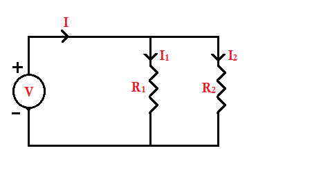
Yes, for sure. And the principle used to find it is known as the current division principle. To explain this, consider the following circuit:
We need to find the currents I1 and I2. First, let’s calculate the equivalent resistance Req, which is given by
                      \[{{R}_{eq}}=\frac{{{R}_{1}}{{R}_{2}}}{{{R}_{1}}+{{R}_{2}}}\]
Now, from the figure, as the voltage across both the resistors is same
\[{{I}_{1}}=\frac{V}{{{R}_{1}}},{{I}_{2}}=\frac{V}{{{R}_{2}}}\]                                                                                  …Equation 1
Voltage (V) of the circuit, V = IReq   …..Equation 2
From Eq.1 and Eq.2, we get,
                            \[{{I}_{1}}{{R}_{1}}={{I}_{2}}{{R}_{2}}=I{{R}_{eq}}=V\]
                            \[\Rightarrow {{I}_{1}}=\frac{I{{R}_{eq}}}{{{R}_{1}}}\]
Putting the value of Req calculated before, we get
\[{{I}_{1}}=\left( {}^{\frac{{{R}_{1}}{{R}_{2}}}{{{R}_{1}}+{{R}_{2}}}}/{}_{{{R}_{1}}} \right)I\]
        \[\Rightarrow {{I}_{1}}=\left( \frac{{{R}_{2}}}{{{R}_{1}}+{{R}_{2}}} \right)I\]
Similarly,${{I}_{2}}=\left( \frac{{{R}_{1}}}{{{R}_{1}}+{{R}_{2}}} \right)I$
This is the principle of current division and the circuit used for this explanation is called a current divider circuit.
To best illustrate this principle, we will take up a numerical example –
Using the current division principle here - 
${{I}_{1}}=\frac{3}{9}\times 3=1A$ ;
${{I}_{2}}=\frac{6}{9}\times 3=2A$
Note that, the larger current (I2) flows through the smaller resistance and the smaller current(I1) flows through the larger resistance. This also proves the inverse proportionality of current and resistance.

HISTORY OF ELECTRICITY


Electricity is one of the most awesome phenomenon’s of nature and the most powerful manifestations of it which we have ever seen is – LIGHTNING.
It’s a 300 year long tale of dazzling experiments by various scientists and engineers which paved the way for the development of this sparkling force of nature.
It was in the beginning of the 18th century when people began to notice the astonishing effects of static electricity with which they could attract feathers with a silk rod or even lightning a candle with the help of static electricity. Initially these tricks were used by magicians to amaze people. But this was not all! Meanwhile there was the invention of Holksby machine which could produce static electricity. The machine was named after the scientists name only. This Holksby machine laid the foundation for the future development of electricity. The machine could produce electricity but the only problem was that there was no way we could store it.
But then around the mid of the 18th century, scientists came up with a new revolutionary invention of lightning jar which could store electricity. This lightning jar was accidently invented by a scientist. The jar took up a little charge and then was capable of giving a heavy shock. This behavior of the jar astonished the scientists. The lightning jar invented at that time closely resembles a modern capacitor. Anyhow, the scientists had found a way to store charge but yet the phenomenon occurring in the jar was unexplained. This was explained by a businessman rational thinker, BENJAMIN FRANKLIN. Franklin is regarded as a scientist but he was a rational thinker who could think on possibly any logical subject. He was the one who explained the phenomenon occurring in the jar and he also proved that the lightning that appears in the sky was electricity and that electricity was also a force of nature.
With all these new ideas and inventions coming up, the whole Europe went electricity crazy!!
The electrical quantity ‘Voltage’ is named after an Italian scientist, ALESSANDRO VOLTA. This is because of the significant contribution he made to the “Enlightment Movement” (name given to the movement for advancement in electricity field). Volta discovered the “VOLTA PILE” which was just a setup of metal discs which could produce some continuous electricity. HE got this idea from the works of another scientist who had worked on the torpedo fish so as to study how the fish produced electricity, but was not able to derive a conclusion. Volta made the same arrangement he saw in the back of the torpedo fish using metal disc and was able to produce continuous electricity, though very small. He had unknowingly created the first battery and this work of Volta was greatly regarded by everyone as this opened the gates for the future inventions.
In 1808, a scientist named Sir Humphrey Davy arranged 800 Volta piles together and connected them with each other. He then drew two terminals out of it. Actually, he had created a battery of the size of a room. This demonstration was set before everyone and as the candles were blown off and Davy touched the two terminals together, a very bright and continuous spark glow out of it which enlightened the whole place and this marked the beginning of a new era. The era in which Humankind was about to harness a mighty force of nature, the Electricity.
Now as the humans had found a way to produce continuous electric current, but there was no way that this discovery could be made use of. And everyone knew, the person who could make something to use this energy was going to be very rich in the near future. And the person to do this was “Thomas Elva Edison” who could see the vast capital generating possibility, if he could develop something of the kind. He gathered a group of talented and young engineers from across the country and established his own research base. His base became the first research base in the world. All of them worked hard day in day out. Due to these continuous efforts Edison was close to developing an electric bulb, but the problem aroused in the selection of the material to be used as filament. He tried everything from platinum to even the beard hairs of his workmen as filament. But the result was not up to the mark. Then, he got an idea from the works of another scientist who was working on the same thing. And that idea was to create a vacuum in the bulb which delayed the burning or damaging of filament and thus he succeeded in making the electric bulb. Edison was now all set up and he decided to make power stations to provide the people with electricity. While Edison was setting up DC power stations all across New York, there was another person, Nikola Tesla, who was not satisfied with Edison’s idea of using DC current. He believed that AC and not DC, was the future. Using the experimental results of Faraday and Fleming, Tesla demonstrated that rotating effect can be produced using AC alone. He used his famous Tesla egg experiment to prove this.
As Tesla was in favor of using AC, Edison favored DC. This led to a rivalry between the two. Edison’s supporters drew new ways to show that AC was a harmful form of electricity and it was life threatening to all the mammals including humans. This was a major setback for Tesla who was working for AC development. At that time, Tesla was financed by businessman George Westinghouse and using his wealth Tesla created an experiment in which he allowed a very high frequency AC current to pass through his body, while he rested on an insulator and the current passed through his body without any pain and it was because of the high frequency, that Tesla was undamaged.
This experiment of Tesla, made a great impact on the people in driving out the fear out of them. Thus, the war of DC and AC came to an end. When Tesla was in his last years, he saw a world which he wanted to build. He saw the world lit up by his work. Tesla died in the year 1943.
Furthermore, in the beginning of the 20th century, there was a mathematician James Clarke Maxwell, who made four equations describing the inter-relationship between electric and magnetic fields. At that time, there were only few people who could understand mathematics at such a level and one of those few was Heinrich Hertz, who took on the task of experimentally proving Maxell’s equations. And he was successful in it!
Then came the discovery of wireless transmission for which the credit was given to Marconi. Though, Marconi received a Nobel Prize for wireless transmission, actually, he was not the one who developed it. It was developed by another scientist named Oliver. Oliver had done both the things that Marconi and Hertz were credited for. But his name just remains a footnote in history, because of his bad luck, I should say.
Following these advancements was the discovery of crystals (semiconductors) which was done by an Indian scientist Jagdish Chander Bose. And these crystals found an enormous use in the future which we witness today. But, nobody knew the potential of these crystals at that time.
With the introduction of the semiconductor materials in electrical and electronic instruments both efficiency and reliability has increased. We now live in a world full of electronics. We can’t even imagine this world without electricity. The understanding of proper and efficient use of electricity took hundreds of years of hard work of handful of great minds and now we are the one who witness this miracle and live in the world which those great pioneers must have imagined at that time.
All the credit goes to them and we should salute them for their mind boggling works.
Related Posts Plugin for WordPress, Blogger...