CONSTRUCTION OF TRANSFORMER

A transformer is the simplest of all electrical devices and this is because of the simplicity and ease in building a transformer. A transformer is indeed very simple in construction, yet the amount of engineering involved in maintaining its elements of construction is vast.
The transformer is made up of the following parts:
  1. Two coils (in case of single phase transformers)
  2. Laminated core
  3. Container for assembled core and windings
  4. Insulating medium
  5. Bushings
These are the main parts of a single phase transformer. In case of a three phase transformer, there are six windings or coils in total and rest the construction is the same as mentioned above.

LAMINATED CORE –

The laminated core is made up of sheet steel laminations which are insulated from each other with minimum air gap between them. The steel which is used to make the core has high silicon content to produce high permeability and low hysteresis loss.

Why the core is laminated?

  1. To provide a continuous magnetic path.
  2. To reduce eddy current losses.
Varnishing or deposition of oxide layer on the surface of steel is done in order to insulate the laminations from each other.
Construction wise on the basis of cores, transformers can be classified as:-
  1. Core type
  2. Shell type

CORE TYPE TRANSFORMERS – 

In core type, there are two vertical legs or limbs over which the coils are wound. The coils used are cylindrical which may be circular, oval or rectangular in shape.
2 D VIEW OF CORE TYPE TRANSFORMER
For large transformers, circular cylindrical type of coils is preferred.
For small transformers, rectangular cylindrical type of coils is preferred.
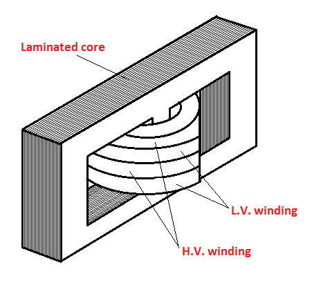
The coils are arranged concentrically. The low voltage winding is placed prior to the high voltage winding. That means, the low voltage winding is first to be wound on the core and then high voltage winding is wound around the low voltage winding.
3 D VIEW OF CORE TYPE TRANSFORMER
In order to insulate the cylindrical windings from the core and from each other, insulating cylinders made of fuller board are used.
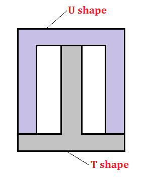
The laminations used are of various types like L, E and U type. Laminations are stacked together just like a pile and their joints are staggered in order to reduce the air gap between them. Larger air gaps increases the reluctance of the core, therefore, minimum air gaps are preferred.


Because of the laminations and insulations, effective core area is reduced by 10%.

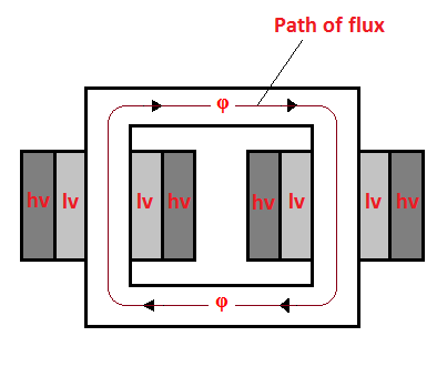
SHELL TYPE TRANSFORMERS –

In shell type transformers, the windings are wound on the central limb of the core. Other two limbs are left as it is. The purpose of these two limbs is to provide low reluctance path.
2 D VIEW OF SHELL TYPE TRANSFORMER
3 D VIEW OF SHELL TYPE TRANSFORMER
The low voltage and high voltage windings are kept one over the other just like a sandwich. Therefore, these type of windings are also called disc or sandwich winding.
Another question that holds importance is – 

Why the cross section of the core is preferred to be circular?

This is because circle has minimum perimeter than any other shape for a given area. Therefore,
  1. Minimum boundary means less length of mean turns.
  2. Less resistance of the winding.
  3. I2R loss is reduced.
  4. Volume of the conductor material reduced and therefore cost is also reduced.
But circular core requires large number of laminations of different sizes to be stacked together. The solution to this problem is the stepped core arrangement, also known as the cruciform core.


SQUARE AND STEPPED CORE CROSS-SECTIONS

This type of core requires the size of the laminations according to the step sizes. As the number of steps increases, the number of sizes of laminations also increases.

CONTAINER AND THE INSULATING MEDIUM –

Now this whole assembly of core and windings is kept in a container, which is called tank. The tank is made air tight and filled with insulating oil. Along with insulation this oil also serves the purpose of cooling the coils of the transformer.

What should be the properties of transformer oil?

  1. Good transformer oil should be free from any type of reagents that can react with the components of transformer.
  2. The oil should be free from moisture.
Because, presence of moisture lowers the dielectric strength of oil and it is not desirable as the oil is used for insulation purpose.
The transformer oil or the insulating medium is that part of the transformer which is taken care, the most. The life of a transformer is dependent on these insulating mediums and therefore they are selected on the basis of their high quality and their ability to preserve that quality even after prolonged use.
Long-time use of oil also causes Sledging. Sledging is the decomposition of oil leading to heavy and dark coloured deposits which can clog the ducts of transformer.
Thus, transformer oil is regularly checked and changed, if required to do so.

BUSHINGS –


Transformer bushings are made of porcelain for small transformers and large transformers are equipped with oil filled condenser bushings. The bushings are used for bringing out the terminals of the windings.

DC TRANSIENT CIRCUITS

What are transient circuits?

The literal meaning of the word ‘transient’ is ‘lasting a very short time’. Transient circuits are those which have their circuit variables changing with time. But this occurs for a very short period of time and therefore they are termed as ‘Transient’.
Further explaining, when a circuit is switched from one condition to another either by change of source or by alteration of circuit elements, the currents and voltages change from their initial values to new values. These changes take a short spell of time to settle to their steady state till further switching is done. This brief spell of time is called transient time and the value of the variables (current and voltage) during this period is called transient value.
When a DC voltage is applied to a ‘capacitor and a series resistor’ OR ‘a inductor and a series resistor’, there is a short period of time immediately after the voltage is connected, during which the circuit variables across the elements are changing. These changing values are called transients.

Why study transient behavior?

Though the circuits exhibiting this transient behavior appear to be very simple and elementary, they are of immense importance to us.
A familiarity with these simple circuits will enable us to predict the accuracy with which the output of an amplifier can follow an input which is changing rapidly with time or to predict how quickly the speed of a motor will change in response to a change in its field current.
The knowledge of the working and performance of these simple circuits will help us to do modifications to the amplifier or motor in order to obtain a more desirable response.

Where are these circuits used?

They find their use as coupling networks in electronic amplifiers, as compensating networks in automatic control systems, as equalizing network in communication channels, and in many other ways.

How to analyze?

These circuits, in general are represented by differential equations. Thus, they can be analyzed by formulating and finding the solutions of the differential equations. The solution of the differential equation represents a response of the circuit is also called the ‘natural response’ of the circuit.

TYPES OF TRANSIENT CIRCUITS –

Transient circuits have been divided into two types:
          1.     First order circuits (characterized by first order differential equations) –
(a)  Series RL circuit
(b) Series RC circuit
          2.     Second order circuit (characterized by second order differential equations) - 
(a)  Series RLC circuit
(b) Parallel RLC circuit

MAXIMUM POWER TRANSFER THEOREM

No circuit in this world is complete without a load, meaning a circuit is most of the times designed to provide power to a load. While our quest is for minimizing power losses in case of power transmission and distribution, still there are areas where maximum power and not efficiency is the major concern. Power transmission and distribution is always done keeping in mind the efficiency of the system and whether the system proves to be economical or not.
But when it comes to electronic and communication networks, very often the goal is to either receive or transmit maximum power (though at reduce efficiency). This is because, here the power involved is mostly a few mill watts or micro watts.
When applied to DC networks, the theorem states that:

STATEMENT: A resistive load will abstract maximum power from a network when the load resistance is equal to the Thevenin resistance as seen from the load. That means when RL=Rth, power delivered to the load will be maximum.

Consider the circuit given below:

Suppose we obtain Vth and Rth of any arbitrary circuit and then connect a load resistance RL across them. Then the power delivered to the load is
\[P={{i}^{2}}{{R}_{L}}={{\left[ \frac{{{V}_{th}}}{{{R}_{th}}+{{R}_{L}}} \right]}^{2}}{{R}_{L}}\]
Now, for any given circuit, thevenin resistance and voltage are fixed. Thus, the power delivered to a load by varying the load resistance can be graphed as shown below:

PROOF OF THEOREM:

Power consumed by the load =${{\left[ \frac{{{V}_{th}}}{{{R}_{th}}+{{R}_{L}}} \right]}^{2}}{{R}_{L}}$
For power to be maximum, $\frac{dP}{d{{R}_{L}}}=0$
\[\Rightarrow \frac{d}{d{{R}_{L}}}\left[ {{\left( \frac{{{V}_{th}}}{{{R}_{th}}+{{R}_{L}}} \right)}^{2}}{{R}_{L}} \right]=0\]
\[\Rightarrow {{V}_{th}}^{2}\left[ \frac{{{\left( {{R}_{th}}+{{R}_{L}} \right)}^{2}}-2{{R}_{L}}\left( {{R}_{th}}+{{R}_{L}} \right)}{{{\left( {{R}_{th}}+{{R}_{L}} \right)}^{4}}} \right]=0\]
\[\Rightarrow {{\left( {{R}_{th}}+{{R}_{L}} \right)}^{2}}=2{{R}_{L}}\left( {{R}_{th}}+{{R}_{L}} \right)\]
                                \[\Rightarrow {{R}_{th}}+{{R}_{L}}-2{{R}_{L}}=0\]
Thus, ${{R}_{th}}={{R}_{L}}$
This shows that the maximum power transfer takes place when the load resistance RL is equal to the thevenin resistance or the internal resistance of the circuit.
As, \[P={{\left[ \frac{{{V}_{th}}}{{{R}_{th}}+{{R}_{L}}} \right]}^{2}}{{R}_{L}}\]
Putting Rth=RL, we get ${{P}_{\max }}=\frac{{{V}_{th}}^{2}}{4{{R}_{th}}}=\frac{{{V}_{th}}^{2}}{4{{R}_{L}}}$
This is the maximum power transferred to the load in case of DC circuits. But when an AC source of internal impedance (R1+jX1) is supplying power to load impedance (RL+jXL). Then, maximum power transfer will take place when
                                 \[\left| {{Z}_{L}} \right|=\left| {{Z}_{i}} \right|\]
i.e. Modulus of load impedance = modulus of internal impedance
Particularly, the maximum power transfer in case of AC is observed when load impedance is the complex conjugate of the source impedance i.e. If internal impedance = R1 + jX1, then for maximum power, load impedance = R1 – jX1.

WHAT IS THE SIGNIFICANCE OF STUDYING MAXIMUM POWER TRANSFER THEOREM?

Studying any topic theoretically without understanding and thinking about its applications is like doing a crime to yourself. As far as, engineering is concerned, it’s all about application.

So where is this theorem used?

Maximum power transfer theorem is mostly utilized in electronic, as mentioned in the introduction of this post. Most of the times, in electronics it is the maximum power that is of more concern than efficiency.
For example, have you seen ‘rabbit ear’ antennas? The one that used to be on TV sets. They receive power from radio waves originating at a transmitter miles away. The antenna does not collect much power. So, the TV receiver is designed to make maximum use of the power provided by the antenna.
Maximum power transfer theorem is used for optimization also. Following the above example, the TV receiver is optimized when its input impedance is matched to the output impedance of the antenna because this gives maximum power to the receiver.

TRANSFORMER

A transformer is a static device which is used to transfer electrical energy from one circuit to another by using the principle of mutual induction. It is generally used to
CIRCUIT SYMBOL OF TRANSFORMER
transform voltage from one level to another. It means transformer can be used to raise or lower down the voltage level by corresponding decrease or increase in the current.
Transformers use the principle of mutual induction. The two circuits are electrically isolated but are magnetically linked to each other by a mutual flux. The transfer of energy takes place without any change in the frequency of the system.

CONSTRUCTION –

Consider the circuit given below:


The rectangular part represents the core, which is a material of high magnetic permeability. The core is laminated in order to reduce eddy current losses. Two coils are wound on the either side of core having turns N1 and N2. The vertical portions of the core are called limbs and bottom portions are called yokes.
The two coils are insulated from each other and the steel core. The whole setup of core and windings is kept in a container which is further insulated from the setup by means of a suitable medium (generally called transformer oil). Transformer oil also serves the purpose of cooling.
Electrical transformer is one of the best examples of those devices which are simplest in their construction, yet serve the most important function in our electrical generation and transmission system.

OPERATION –

When an alternating current is passed through coil 1(primary coil), it produces a magnetic flux. Since, the current is alternating in nature a changing magnetic flux is produced. This changing magnetic flux induces a voltage across the ends of the coil 2 (secondary coil), which is governed by the relation, $e=-\frac{d\phi }{dt}$ .
Simply stating, changing current leads to changing magnetic field which in turn leads to the voltage induced in the secondary circuit. Thus, energy is transferred from one circuit to the other.

IDEAL TRANSFORMER –

To study about transformers, we generally consider the ideal case. The ideal case of a transformer should have the following properties:
  1. The magnetic permeability of the core should be infinite. I.e. no magneto motive force (mmf) is needed to setup the flux.
  2. Leakage flux should be zero. i.e. the flux is confined within the core and entirely links both the windings.
  3. Resistances of windings should be zero.
  4. There are no losses due to resistance, eddy currents and hysteresis.


In short, an ideal transformer has no losses and stores no energy. The phasor diagram for an ideal transformer is as follows:
However, there is no such transformer that exists and is ideal in nature. The ideal case is just to be used for study purpose. It is that no transformer has 100% efficiency, but there are transformers which have efficiency of 99.75% (very close to ideal one).

EMF EQUATION OF TRANSFORMER –

When an alternating voltage is applied to the primary of a transformer, a varying magnetic flux is setup. Let this varying flux be represented by
                      \[\phi ={{\phi }_{m}}\sin \omega t={{\phi }_{m}}\sin 2\pi ft\]
Where ${{\phi }_{m}}$ = maximum flux
               f= frequency of variation of flux
By faraday’s law of electromagnetic induction, the induced emf in winding of N turns is given by,
                \[E=-N\frac{d\phi }{dt}=-N\frac{d}{dt}({{\phi }_{m}}sin\omega t)\]
              \[=-N\omega {{\phi }_{m}}\cos \omega t=N\omega {{\phi }_{m}}\sin (\omega t-\frac{\pi }{2})\]
Thus, maximum value of induced emf, ${{E}_{m}}=N\omega {{\phi }_{m}}$
Rms value of induced emf, ${{E}_{R}}=\frac{{{E}_{m}}}{\sqrt{2}}=\frac{N\omega {{\phi }_{m}}}{\sqrt{2}}=\frac{2\pi fN{{\phi }_{m}}}{\sqrt{2}}$
                                               \[{{E}_{R}}=4.44fN{{\phi }_{m}}\]

TRANSFORMATION RATIO (K) –

Transformation ratio is given by ratio of secondary voltage to the primary voltage. To obtain this ratio:
The induced emf’s in primary and secondary windings (rms values) is given by:
                                    \[{{E}_{1}}=4.44f{{N}_{1}}{{\phi }_{m}}\] and
                                        \[{{E}_{2}}=4.44f{{N}_{2}}{{\phi }_{m}}\]
Thus transformation ratio is, $\frac{{{E}_{2}}}{{{E}_{1}}}=\frac{4.44f{{N}_{2}}{{\phi }_{m}}}{4.44f{{N}_{1}}{{\phi }_{m}}}$
\[\Rightarrow \frac{{{E}_{2}}}{{{E}_{1}}}=\frac{{{N}_{2}}}{{{N}_{1}}}=\frac{{{V}_{2}}}{{{V}_{1}}}=K\]
This is for a two winding transformer. If the transformer has three windings (primary, secondary and tertiary), then the ratio of emf’s is given by E1:E2:E3:: N1:N2:N3.

CURRENT

Electric current is defined as the amount of charge flowing through a conductor in a unit time. Basically, it is just the flow of electrons under the influence of an electric field. It is represented by the formula- \[I=\frac{Q}{t}\] 
where,   I = current
            Q = charge flowing through the conductor
             t = time in seconds 
The direction of current is always taken from positive terminal of the battery to the negative terminal of the battery.
Current in a conductor can also be represented by the formula-
\[I=Ane{{v}_{d}}\]
where, A = area of cross-section of the conductor
  n = number of free electrons
  e = charge on an electron
  ${{v}_{d}}$ = drift velocity of electrons
Drift velocity is defined as the velocity which an electron attains due to an electric field.

What causes the movement of electrons?

When potential difference is applied across a conductor, an electric field is set up, which causes the movement of electrons.

The positive charges developed across the end A of the conductor attracts the electrons, thus setting up a current which is opposite to the direction of movement of electrons.

TYPES OF CURRENT

There are two types of current-
  1. DC current
  2. AC current

DC current-

DC stands for Direct Current. This type of current in only one direction. It is produced by sources such as batteries, thermocouple, solar cells, etc.

AC current-

AC stands for alternating current. In AC, the movement of electric charges periodically reverses its direction. This means that the polarity of AC source changes periodically. The usual waveform of an AC power circuit is a sine wave. In general, AC form is more widely used than DC. Mostly, AC is generated and transmitted for all industrial, commercial and residential uses. But, in some places DC is required in place of AC.

Unit used-

Current is usually measured in Amperes. This unit of current was named after the famous scientist Andre Marie Ampere. Symbolically, it is written as capital 'A'. The magnitude of current can be measured by an instrument called Ammeter.
For example, 1A, 2A, 20A, etc.  

MAIN EFFECTS OF ELECTRIC CURRENT-

The three main effects of electric current are-
  1. Magnetic effect
  2. Chemical effect
  3. Heating effect
Some practical applications of these effects include-
  • Magnetic effects: Bells, relays, motor, generator, transformer, telephones, car ignition and lifting magnets.
  • Chemical effect: Primary & secondary cells and electroplating.
  • Heating effect: Cookers, water heaters, electric fires, irons, furnaces, kettles and soldering irons.


RESISTANCE

SYMBOL OF RESISTANCE
Electrical resistance is defined as the obstruction offered by a material towards the flow of electric current. Every substance possesses some or more of resistance. None of the materials on this earth is fully conducting or superconducting. It is measured using a ohmmeter and its unit in which it is measured is $\Omega $ (ohms).
Based on the property of resistance, materials are classified as:

  • Conductors
  • Insulators
  • Semiconductors 

CONDUCTORS-

Conductors are the substances (generally metals) which provide very low resistance to current flow. Their resistivity is of the order of ${{10}^{-8}}\Omega m$. Silver is the best conductor with resistivity of $1.5\times {{10}^{-8}}\Omega m$.

INSULATORS-

Insulators are the substances (generally non-metals) which provide high resistance to the flow of current. Their resistivity is of the order of ${{10}^{8}}-{{10}^{16}}\Omega m$. However, they can be made conducting, but at very high voltages. This is because every material undergoes electrical breakdown at a particular voltage level.

SEMICONDUCTORS-

They are a special class of materials whose resistivity lies in between those of conductors and insulators. Their resistivity ranges from ${{10}^{-4}}-{{10}^{5}}\Omega m$. But, the resistivity of these materials varies with factors such as doping concentration and temperature variation.

ON WHAT FACTORS DOES RESISTANCE DEPEND?

Consider a wire of length l and cross-sectional area A. Then, the resistance of that wire is given by:-

\[R=\rho \frac{l}{A}\]
where,  
R - resistance of material
l - length of wire
A - area of cross section of wire
$\rho $  - resistivity of the material
Thus, resistance R depends on:
  1. Length
  2. Area of cross-section
  3. Type of the material and,
  4. Temperature of the material

The fourth factor i.e. Temperature; determines the resistance of the material at that point of time.


TEMPERATURE COEFFICIENT OF RESISTANCE-

Generally, as the temperature of a conductor material increases, its resistance also increases.
The temperature coefficient of resistance of a material is the increase in the resistance of a 1$\Omega $ resistor of that material when it is subjected to a rise of temperature of 1℃. Its symbol is α.
\[{{R}_{\theta }}={{R}_{0}}(1+{{\alpha }_{0}}\theta )\]
where,  ${{R}_{0}}$ - resistance at 0℃.
                ${{R}_{\theta }}$ - resistance at $\theta $℃.
                ${{\alpha }_{0}}$ - temperature coefficient at 0℃.
Negative sign of $\alpha $  indicates resistance will decrease when temperature rises (resembles an insulator). 
Positive sign of $\alpha $ indicates rise of resistance with temperature (resembles a conductor).

WHAT IS THE CAUSE OF RESISTANCE IN MATERIALS?

As, voltage is applied across a material, an electric field is set up which initiates the movement of electrons. These moving electrons collide with the atoms present in the material and thus their flow is obstructed. This is what is called Resistance.The low resistance of the conductors is due to the fact that they possess free electrons in them, which is not the case with insulators.
INSIDE A CONDUCTOR (METAL) WHEN CURRENT FLOWS

Particularly, taking into consideration the case of conductors, the diagram above shows the free electrons moving past the positively charged atoms (Kernels) and thus experience hindrance in their movement. Since, the number of free electrons in the metals are very large; their conductivity is high.

SUPERCONDUCTIVITY-

Seeing the needs and importance of negligible resistance in future, so as to prevent losses in transmission, it is obvious that superconductivity and not conductivity is the future! Superconductors are the material which have zero resistance or in other words infinite conductance. But, unfortunately there is no material like that , which is in existence naturally.However, certain conductors at very low temperatures exhibit the property of superconductivity. For example, if mercury is cooled below 4.1K, it loses all its electrical resistance and becomes a superconductor. But, such low temperatures are not available naturally anywhere. Efforts are being made on very large scale to develop superconductor materials which can perform well in normal environmental conditions.


VOLTAGE

Voltage or potential difference is the energy required to move a unit charge through an element. It is measured in volts (V). The instrument used to measure voltage between two points is known as voltmeter.
Another term used in conjunction with voltage is 'EMF'. But what is EMF?
EMF stands for electromotive force. It is defined as the potential difference that exists between the terminals of a battery when it is not connected to a load (i.e. the cell is on 'no load'). 


SYMBOLS USED

Consider a charge +Q in space. The electric field due to this charge is coming out of it as defined conventionally. Let a unit charge 'q' be made to move from point A to B. Then, the energy move this unit charge from point A to B is defined as the voltage Vab.

In other words, Voltage or potential difference is defined as the amount of work that is needed to be done per unit charge, to move the charge from one point to another (i.e. A to B).
Mathematically,\[V=\frac{W}{q}\]
i.e. 1 Volt = 1 Joule/coulomb = 1 Nm/Coulomb
According to ohm's law, voltage between two points is given by the product of current through that path and the resistance offered by the path.
\[V=IR\]
Consider the figure given below:
It shows that 'a' is at a higher potential than point 'b'. This means that there is a drop of 9 volts from point a to b.

TYPES OF VOLTAGE - 

Like electric current, a constant voltage is called a DC voltage and is represented by V, whereas a sinusoidally time varying voltage is called an AC voltage and is represented by v.
The voltage produced by a battery is DC voltage and that produced by an electric generator is AC voltage.

HYDRAULIC ANALOGY - 

The word 'voltage' is analogous to 'pressure' and 'tension'. Consider two tanks filled with different heights of water in them and connected to each other. Then, the tank in which water is filled to a greater height will have more potential than the other tank with lower water height. Water will flow from tank A to tank B as the tap is opened.This is because of the potential difference between the two tanks.
The above mentioned example best illustrates a battery in which there is difference of potential between positive and negative terminals which causes the flow of charges from one terminal to the other until the charges get neutralised.
Similarly, other terms such as current and resistance can also be explained using water analogy method for a more clear and better undderstanding.
  

OHM'S LAW

GEORGE SIMON OHM
In the year 1827, a German Physicist, George Simon Ohm, published a pamphlet entitled "Die galvanische kette mathematisch bearbeitet" meaning "The Galvanic circuit investigated mathematically".
This pamphlet contained the results of one of the first efforts to measure current and voltage and to describe and relate them mathematically. One result was a statement of the fundamental relationship we now call 'Ohm's law'. Ohm's law is the most fundamental law in Electrical engineering. It states that
" The potential difference between the two ends of a conductor is directly proportional to the current flowing through it, provided its temperature and other physical parameters remain unchanged". That is,
\[V\alpha I\] or \[V=RI\]
The constant of proportionality R is called the resistance of the conductor. Its unit is ohm($\Omega $).
Another way of stating ohm's law is $I\alpha V$ or $I=GV$.
The constant of proportionality G is called the conductance of the conductor. It is the reciprocal of resistance and its SI unit is Siemens(S).

OHM'S LAW IN GRAPHICAL FORM - 

OHM'S LAW IN GRAPHICAL FORM
Ohm's law in graphical form is shown in the adjacent figure. The voltage is shown as independent variable(cause) and current as dependent variable(effect). The slope of the line is the reciprocal of resistance (1/R), and is called conductance.
A conductor showing straight line V-I characteristics is said to have a linear resistance.


SHORT CIRCUIT AND OPEN CIRCUIT - 

If the V-I characteristic graph reads,
Then V=0, and R=0 with I$\ne $0 . It represents a short circuit and is represented by the circuit as shown in the figure given below.
If the V-I characteristic graph reads,
Then V$\ne $0, I=0 and R= $\infty $ . It represents an open circuit and is represented by the circuit as shown in the figure given below.
    Ohm's law alone is not enough to analyze all the complex circuits in electrical. There are some more laws such as Kirchhoff's law which help in better analyzing the circuits. These laws will be discussed in the further posts. 
Related Posts Plugin for WordPress, Blogger...