Norton’s
theorem was published in the year 1926 by Edward Lawry Norton, an American
engineer at bell telephone laboratories. This theorem was published about 43
years after Thevenin’s theorem was published.
Norton’s
theorem is similar or we can say dual of the Thevenin’s theorem. Briefly
speaking, at one end where Thevenin’s theorem reduces a linear two terminal
network to an equivalent constant voltage source and series resistance;
Norton’s theorem reduces or replaces the network by an equivalent constant
current source and a parallel resistance.
STATEMENT:
Norton’s
theorem states that a linear two terminal circuit can be replaced by an
equivalent circuit consisting of a current source IN in parallel
with a resistor RN, where
IN
is the short circuit current through the terminals.
RN
is the equivalent resistance at the terminals when the independent sources are
turned off.
HOW TO NORTONIZE A GIVEN CIRCUIT?
To
illustrate this procedure, consider a simple circuit as follows:

Now follow
the step by step procedure:
1. Remove the resistance (if any) across
the two given terminals and put a short circuit across them. In this case,
there is no resistance at the terminals which follows from the diagram below.
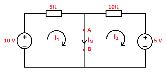
2. Compute the short circuit current (ISC)
or in other words Norton current (IN). Using the figure in step 1
above,
${{I}_{N}}={{I}_{1}}+{{I}_{2}}=\frac{10}{5}+\frac{5}{10}=2.5A$

Keep in mind
that only independent sources need to be removed when calculating effective
resistance while the dependent sources are left intact as they depend on other
circuit variables.
When
dependent sources are present, follow the same procedure as mentioned in the
Thevenin’s theorem.
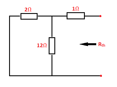
Thus, after
turning off the independent sources Req comes out to be
${{R}_{eq}}={{R}_{N}}=5\Omega
\parallel 10\Omega =\frac{5\times 10}{5+10}=\frac{10}{3}\Omega $
Note that,
the procedure for finding the RN is the same as Rth
(Thevenin’s resistance) which implies that Rth = RN.
4.
Now, connect the current source (IN
or ISC) in parallel with Norton resistance to give Norton’s
equivalent circuit.

5. The load current IL can be found
using the current divider principle i.e.
\[{{I}_{L}}=\left(
\frac{{{R}_{N}}}{{{R}_{N}}+{{R}_{L}}} \right){{I}_{N}}\]
RELATIONSHIP BETWEEN THEVENIN’S AND NORTON’S EQUIVALENT CIRCUITS –
As we find RN in the same way as Rth,
therefore, RN = Rth.
And ${{I}_{N}}=\frac{{{V}_{th}}}{{{R}_{th}}}\text{ or
}{{V}_{th}}={{R}_{N}}{{I}_{N}}$
This
equation is very useful as it can be applied to find the output impedance of a
source. Practically, it is not possible to get inside a circuit and turn off
internal sources. But we can measure open circuit output voltage and current
that would flow when the output terminals are shorted.