
A
transformer is the simplest of all electrical devices and this is because of
the simplicity and ease in building a transformer. A transformer is indeed very
simple in construction, yet the amount of engineering involved in maintaining
its elements of construction is vast.
The
transformer is made up of the following parts:
1. Two coils (in case of single phase
transformers)
2. Laminated core
3. Container for assembled core and
windings
4. Insulating medium
5. Bushings
These are
the main parts of a single phase transformer. In case of a three phase
transformer, there are six windings or coils in total and rest the construction
is the same as mentioned above.
LAMINATED CORE –
The
laminated core is made up of sheet steel laminations which are insulated from
each other with minimum air gap between them. The steel which is used to make
the core has high silicon content to produce high permeability and low
hysteresis loss.
Why the core is laminated?
1. To provide a continuous magnetic
path.
2. To reduce eddy current losses.
Varnishing
or deposition of oxide layer on the surface of steel is done in order to
insulate the laminations from each other.
Construction
wise on the basis of cores, transformers can be classified as:-
1. Core type
2. Shell type
CORE TYPE
TRANSFORMERS –
In core
type, there are two vertical legs or limbs over which the coils are wound. The
coils used are cylindrical which may be circular, oval or rectangular in shape.
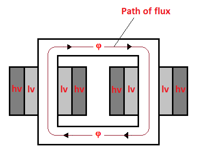 |
| 2 D VIEW OF CORE TYPE TRANSFORMER |
For large
transformers, circular cylindrical type of coils is preferred.
For small
transformers, rectangular cylindrical type of coils is preferred.
The coils
are arranged concentrically. The low voltage winding is placed prior to the
high voltage winding. That means, the low voltage winding is first to be wound
on the core and then high voltage winding is wound around the low voltage
winding.
In order to insulate the cylindrical windings from the core and from
each other, insulating cylinders made of fuller board are used.
 |
| 3 D VIEW OF CORE TYPE TRANSFORMER |
The laminations used are of various types like
L, E and U type. Laminations are stacked together just like a pile and their
joints are staggered in order to reduce the air gap between them. Larger air
gaps increases the reluctance of the core, therefore, minimum air gaps are
preferred.


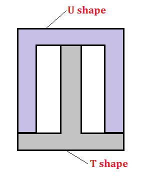
Because of
the laminations and insulations, effective core area is reduced by 10%.
SHELL TYPE TRANSFORMERS –
In shell
type transformers, the windings are wound on the central limb of the core.
Other two limbs are left as it is. The purpose of these two limbs is to provide
low reluctance path.
The low voltage and high voltage windings are kept one
over the other just like a sandwich. Therefore, these type of windings are also
called disc or sandwich winding.
 |
| 2 D VIEW OF SHELL TYPE TRANSFORMER |
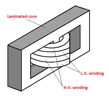 |
| 3 D VIEW OF SHELL TYPE TRANSFORMER |
Another
question that holds importance is –
Why the cross section of the core is preferred to be circular?
This is
because circle has minimum perimeter than any other shape for a given area.
Therefore,
1. Minimum boundary means less length of
mean turns.
2. Less resistance of the winding.
3. I2R loss is reduced.
4. Volume of the conductor material
reduced and therefore cost is also reduced.
But circular
core requires large number of laminations of different sizes to be stacked
together. The solution to this problem is the stepped core arrangement, also
known as the cruciform core.


SQUARE AND STEPPED CORE CROSS-SECTIONS
This type of
core requires the size of the laminations according to the step sizes. As the
number of steps increases, the number of sizes of laminations also increases.
CONTAINER AND THE INSULATING MEDIUM –
Now this
whole assembly of core and windings is kept in a container, which is called
tank. The tank is made air tight and filled with insulating oil. Along with
insulation this oil also serves the purpose of cooling the coils of the
transformer.
What should be the properties of transformer oil?
1. Good transformer oil should be free
from any type of reagents that can react with the components of transformer.
2. The oil should be free from moisture.
Because,
presence of moisture lowers the dielectric strength of oil and it is not
desirable as the oil is used for insulation purpose.
The
transformer oil or the insulating medium is that part of the transformer which
is taken care, the most. The life of a transformer is dependent on these
insulating mediums and therefore they are selected on the basis of their high
quality and their ability to preserve that quality even after prolonged use.
Long-time
use of oil also causes Sledging. Sledging is the decomposition of oil leading
to heavy and dark coloured deposits which can clog the ducts of transformer.
Thus,
transformer oil is regularly checked and changed, if required to do so.
BUSHINGS –
Transformer
bushings are made of porcelain for small transformers and large transformers
are equipped with oil filled condenser bushings. The bushings are used for bringing
out the terminals of the windings.


