Thevenin’s
theorem was first proposed by a French telegraph engineer M.L.thevenin in 1883.
Many a times we come across situations where we need to find the response
(current, voltage, power) of a circuit against different values of load.
Simplest example of this situation is in our homes; we connect different types
of electrical devices (loads) to a single socket time and again. But then, what
if we need to analyze the same circuit with different loads? It’s a tedious job
you know!
WHAT THIS
THEOREM DOES FOR US?
Thevenin’s
theorem provides a mathematical technique for replacing a given network by a
single voltage source with a series resistance, as viewed from the two output
terminals.
STATEMENT:
Thevenin’s
theorem states that a linear two terminal circuit can be replaced by an
equivalent circuit consisting of a voltage source (Vth) in series
with a resistor Rth, where
Vth
– is the open circuit voltage as viewed from output terminals.
Rth
– is the equivalent resistance at the terminals when the independent sources
are turned off.
Thevenin’s
theorem is a powerful tool in circuit analysis. It helps in replacing a large
and complex circuit with a simple circuit consisting of voltage source and a
series resistance.
HOW TO
THEVENIZE A GIVEN CIRCUIT?
Consider the
following circuit:
1. Temporarily remove the load
resistance RL through which current is required.
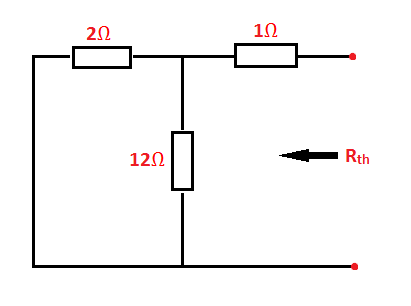
2. Compute the equivalent resistance as
seen from the open terminals. Replace (turn off) independent voltage sources by
short circuit and independent current sources by open circuit; and then
calculate Req or Rth.
NOTE: If the network has dependent sources, we turn off all independent sources, leaving the dependent sources intact, as they are controlled by circuit variables. In this case we can proceed in two ways to find Rth:
NOTE: If the network has dependent sources, we turn off all independent sources, leaving the dependent sources intact, as they are controlled by circuit variables. In this case we can proceed in two ways to find Rth:
1.
Apply
a voltage source V0 at terminals a and b and determine the resulting
current i0. Then Rth=V0/i0.
2.
Insert
a current source i0 at terminals a – b and find terminal voltage V0.
Again Rth= V0/i0.In either
approach we may assume any value of V0 and i0.
3. Considering the circuit mentioned
above with independent sources; after finding Rth, find the open
circuit voltage Voc which appears across the two terminals a – b.
This is Vth.
4. Replace the entire network by a
single thevenin source, whose voltage is Vth or Voc and
internal resistance Rth or R.
5. Connect RL back to its
terminals from where it was previously removed.
6. Finally, calculate the current
flowing through RL, using the equation –
I = Vth/(Rth+RL) or
I = Voc/(Ri+RL)
To find Vth –
$-16+2{{i}_{1}}+12({{i}_{1}}-{{i}_{2}})=0$ And ${{i}_{2}}=-1A$
Solving for i1, we get
$-16+2{{i}_{1}}+12{{i}_{1}}+12=0$
${{V}_{th}}=12({{i}_{1}}-{{i}_{2}})=12(\frac{2}{7}+1)=12\times
\frac{9}{7}=15.42V$


